Design and Simulation of a Tesla Model 3 (PMSM motor)
This project presents a MATLAB/SIMULINK model of a battery electric vehicle (BEV) powered by a PMSM motor. I’ve chosen to model the Tesla Model 3 (TM3) and have simulated its characteristics for this project. Becoming the world's all-time best selling EV in 2020, the invention of TM3 has been inspiring to me.
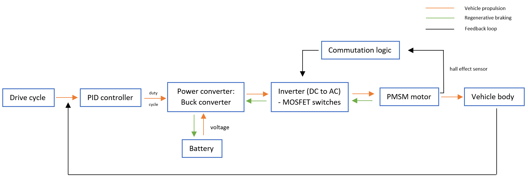
How a BEV with a PMSM motor (trapezoidal commutation) is typically modelled:

Expanded overview of the entire model:

Short summary of how this model works:
The PID controller continuously adjusts the acceleration and braking of the vehicle to meet the demands of the reference drive cycle (WLTP Class 1). It is connected to the Buck converter powered by a battery, which needs to step down the voltage accordingly to power the MOSFET switches in the Inverter circuit. The acceleration command is used as a duty cycle input for the buck converter to modulate the voltage accordingly. A PMSM motor needs 3-phase AC to run, and thus the Inverter converts DC from the battery to 3-phase AC using six inverter switches that work in pairs. Which pair of coils need to be energized inside the PMSM motor is detected by a hall effect sensor, which then uses the rotor position information to apply a commutation logic in order to turn switches on/off (animation shown below). The motor generates angular velocity and torque to power the wheels and propel the vehicle forward.
Condensed into subsystems:

Operation and working principle of PMSM motor:
-

3-phase inverter connected to PMSM motor
The motor consists of a permanent magnet (the rotating red and blue poles) as part of the rotor, and coil windings (3 sets - A, B, and C) as part of the stator.
A DC supply is given to a set of coil combinations (S1 and S6 for instance), energizing them and making them an electromagnet in a magnetic arena. The operation is a simple interaction between the permanent magnet and the electromagnet A/B/C, which exerts a force on the rotor, thereby rotating it to produce a torque
-

Commutation logic
H = high side = North pole; L = low side = South pole; AH turned on would mean A is acting as the North pole
There are 6 sets of combinations as presented in the table above that energize different sets of coils to keep the rotor rotating.
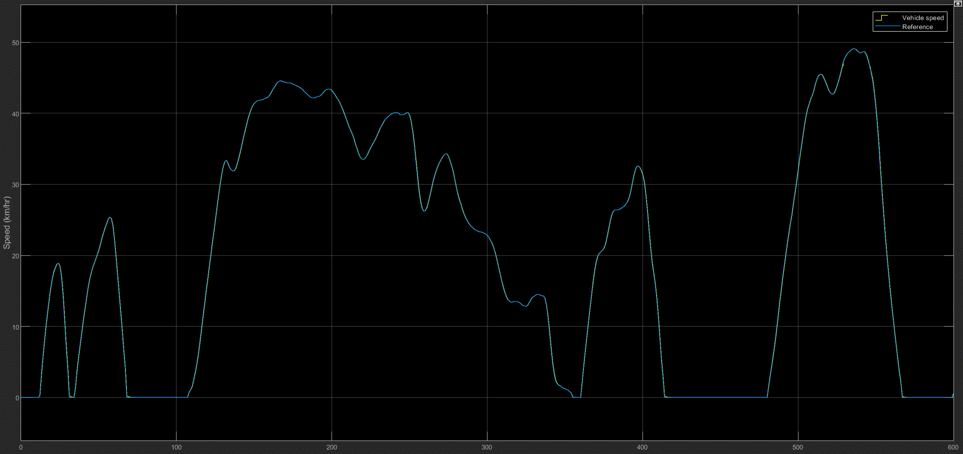
Results of the simulation: Tracking ability

The vehicle tracks the reference drive cycle perfectly. This results in optimized performance and excellent resource management.
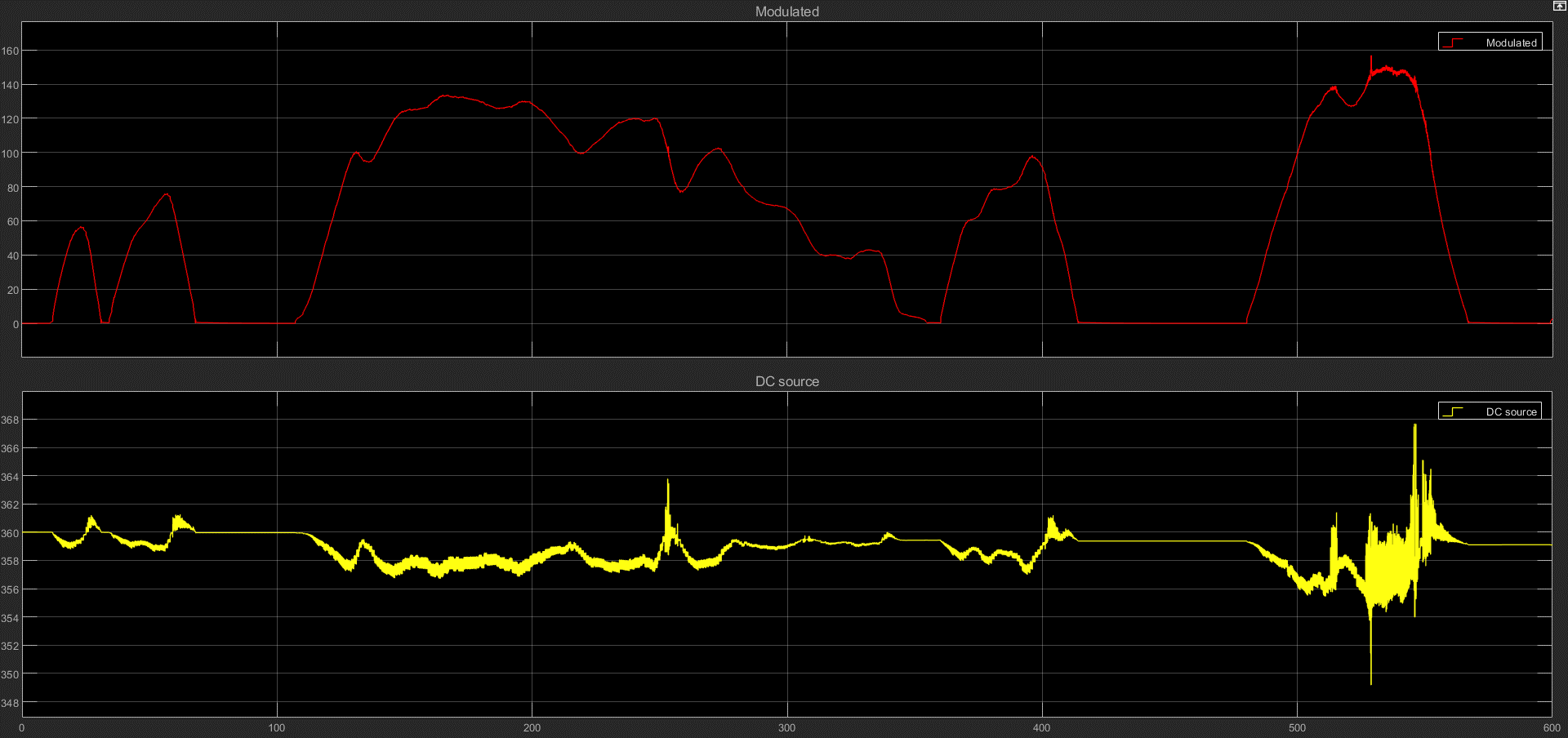
Buck converter in operation: modulated voltage

The battery generates a constant voltage of 350-360V, and the buck converter modulates that to 0-150V as per the requirements of the motor and vehicle.
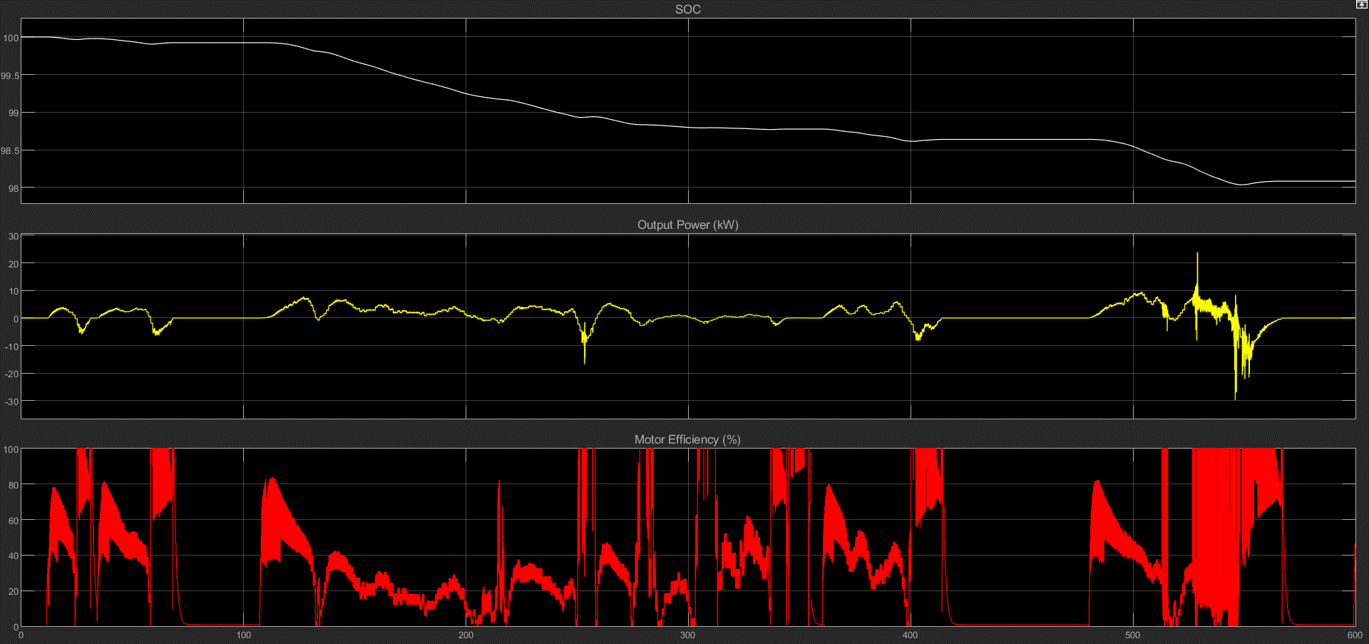
Performance parameters:

SOC depletes from 100 to 98% in about 10 minutes. Would've been lesser had there been regenerative braking modelled, as energy would've been recovered back to charge the battery.
Average output power for this drive cycle is lesser than 10kW, apart from a few spikes towards the end.
Motor efficiency, although very unstable and fluctuating, averages between 40 - 80%. Current fluctuations need to be reduced.
