Design and Simulation of a Fuel Cell Hybrid Electric Vehicle, powered by three propulsion sources — Fuel Cell, Battery, and Ultracapacitor.
FCHEVs with two propulsion sources, namely fuel cell and battery, exist in the form of a few popular vehicles today. Honda Clarity, Hyundai Nexo, and probably the most popular one yet, the Toyota Mirai 2021. The way these sources work together is — the fuel cell covers the low & medium power demand, while the battery covers the high power demand.
However, this is not ideal for either of them. A FC operates best in the mid-power demand region, while the battery's optimal operation happens in the low power demand region. Operating both these sources outside their best performing regions leads to more fuel consumption, higher charge/discharge current, faster degradation of both FC and battery, to name a few drawbacks.
This is where the idea of a third propulsion source comes in — an ultracapacitor. This reduces the load on the battery and allows the FC to operate in its most efficient region. It bridges the gap created by a FC's slow dynamics and a battery's limited ability to consistently handle transient surges, making the system much more efficient overall.
This model henceforth presents the modelling of a FCHEV with three propulsion sources managed by a load-following energy management strategy, with the purpose of giving light to a potential future possibility.
Overview of the entire model:
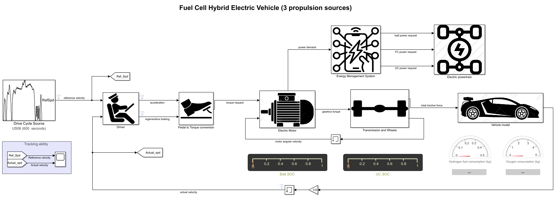
Short summary of how this model works:
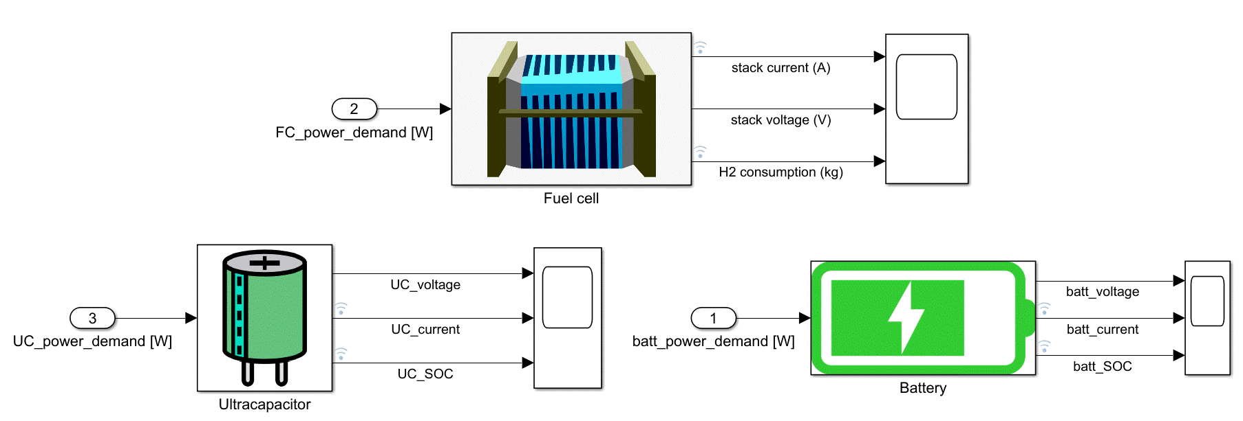
The Driver block is a PID controller which tries to meet the demands of the US06 Drive Cycle by continuously adjusting the acceleration and braking of the vehicle. Once acceleration and brake commands are converted into torque requests for the motor using its data, the motor generates torque and power requests for the electric powertrain and energy management system (EMS). The EMS is an algorithm that, based on many factors, evaluates which propulsion source should generate how much power to meet the demand. The three propulsion sources then follow those commands accordingly to fuel the electric motor to propel the vehicle and satisfy demands.
Electric powertrain:
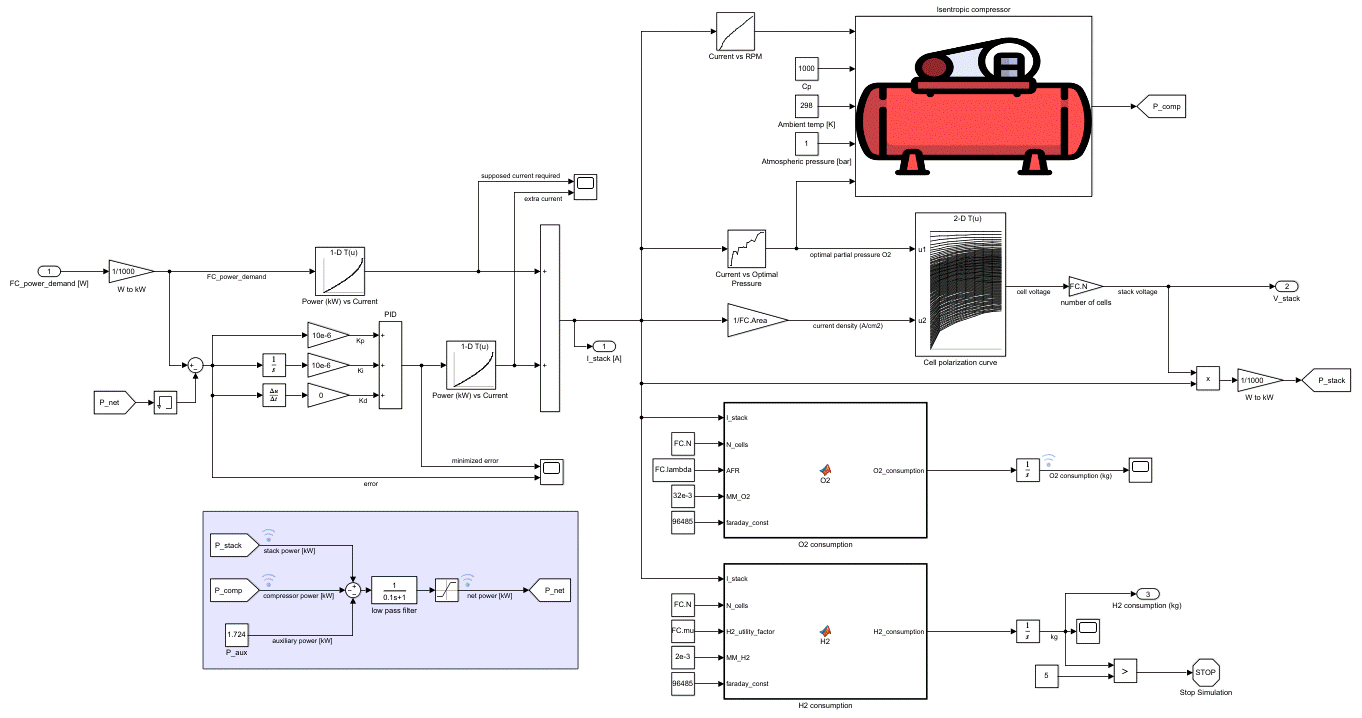
Fuel cell stack:
Energy storage systems: Battery and Ultracapacitor
Battery (above) and Ultracapacitor (figure below) have been modelled using their governing equations — State of Charge, Current, Voltage, etc.
Energy Management System:
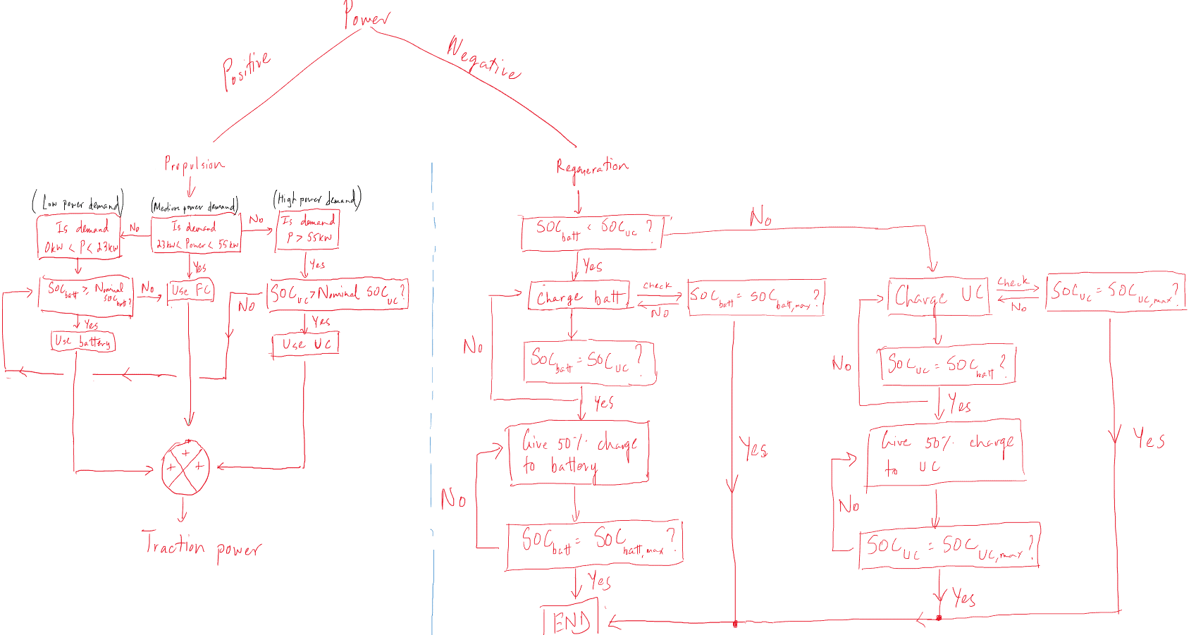
This flowchart (figure above) takes into consideration all possibilities. Every situation is then modelled and mapped out (figure below) to operate all three propulsion sources as efficiently as possible.

How the three sources distribute the power demand:
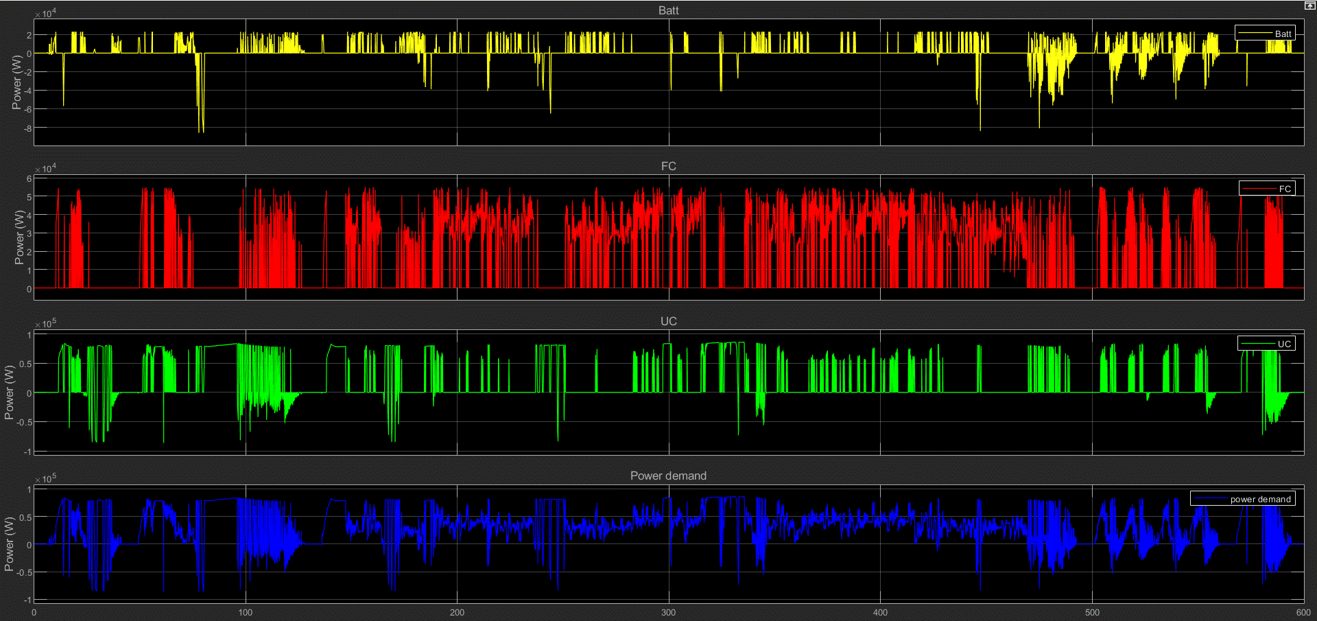
Power demand is from -80kW to 80kW
As long as battery's SOC is greater than 40%, it handles the power demand from 0kW - 23kW. If its SOC is below 40%, the FC is the backup source of power.
FC handles the power demand from 23kW - 55kW
As long as UC's SOC is greater than 40%, it handles the power demand for 55kW - 80kW (and beyond if needed). If its SOC is below 40%, battery is the backup source of power. If battery's SOC is also below 40%, then FC is the backup source of power.
For negative power demand, both battery and UC absorb the regenerative braking energy according to their SOC levels. If battery's SOC is lesser than that of UC's, then the battery will absorb the regenerative energy to charge itself up to the same SOC as the UC, and vice versa. Once they are both at the same SOC, the regenerative energy will be distributed equally. Regenerative energy is only wasted as heat when the SOC of both sources is greater than or equal to 90%.
Performance: Tracking ability
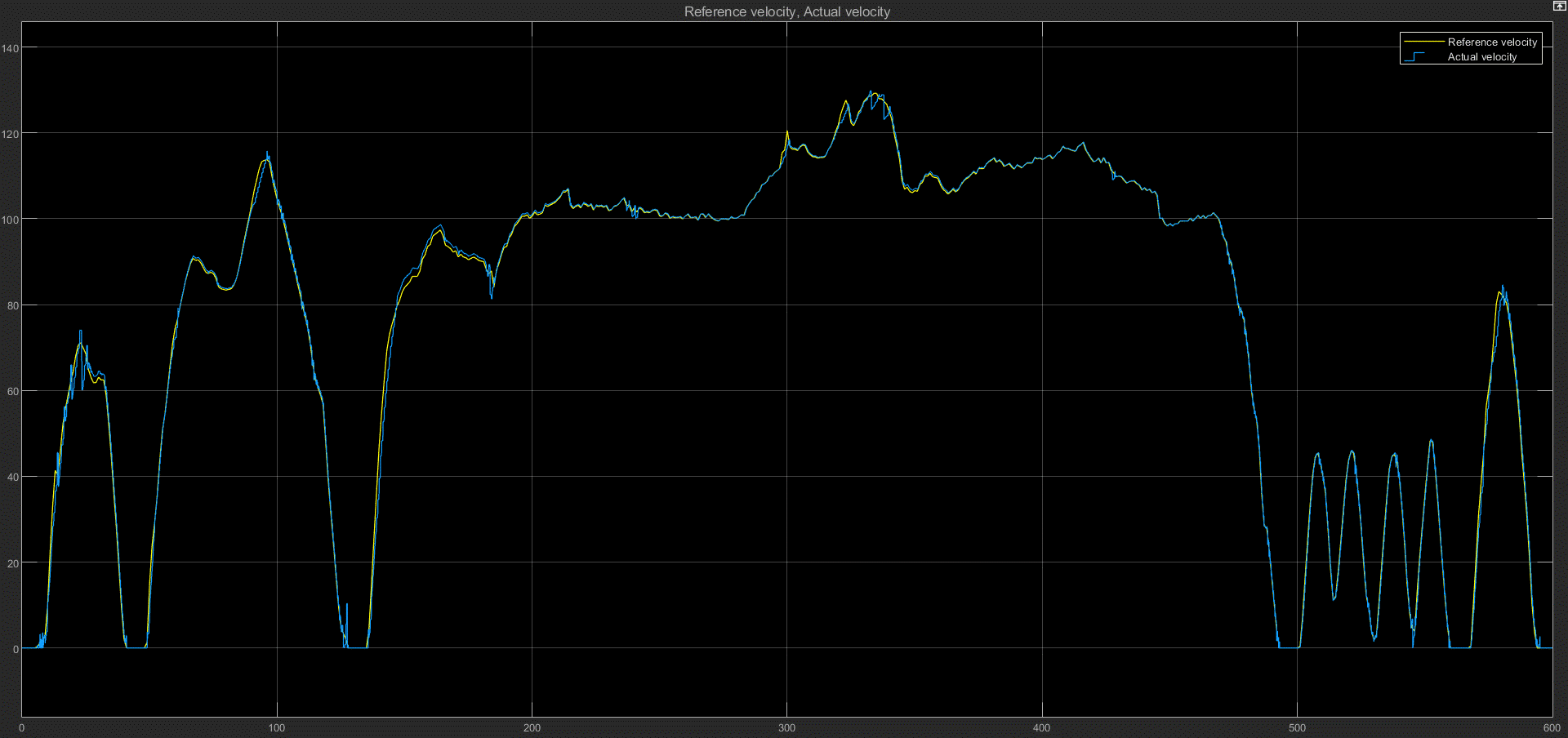
Driver tracks the reference US06 drive cycle quite well. Further optimization will allow better tracking ability.
Hydrogen and oxygen consumption:
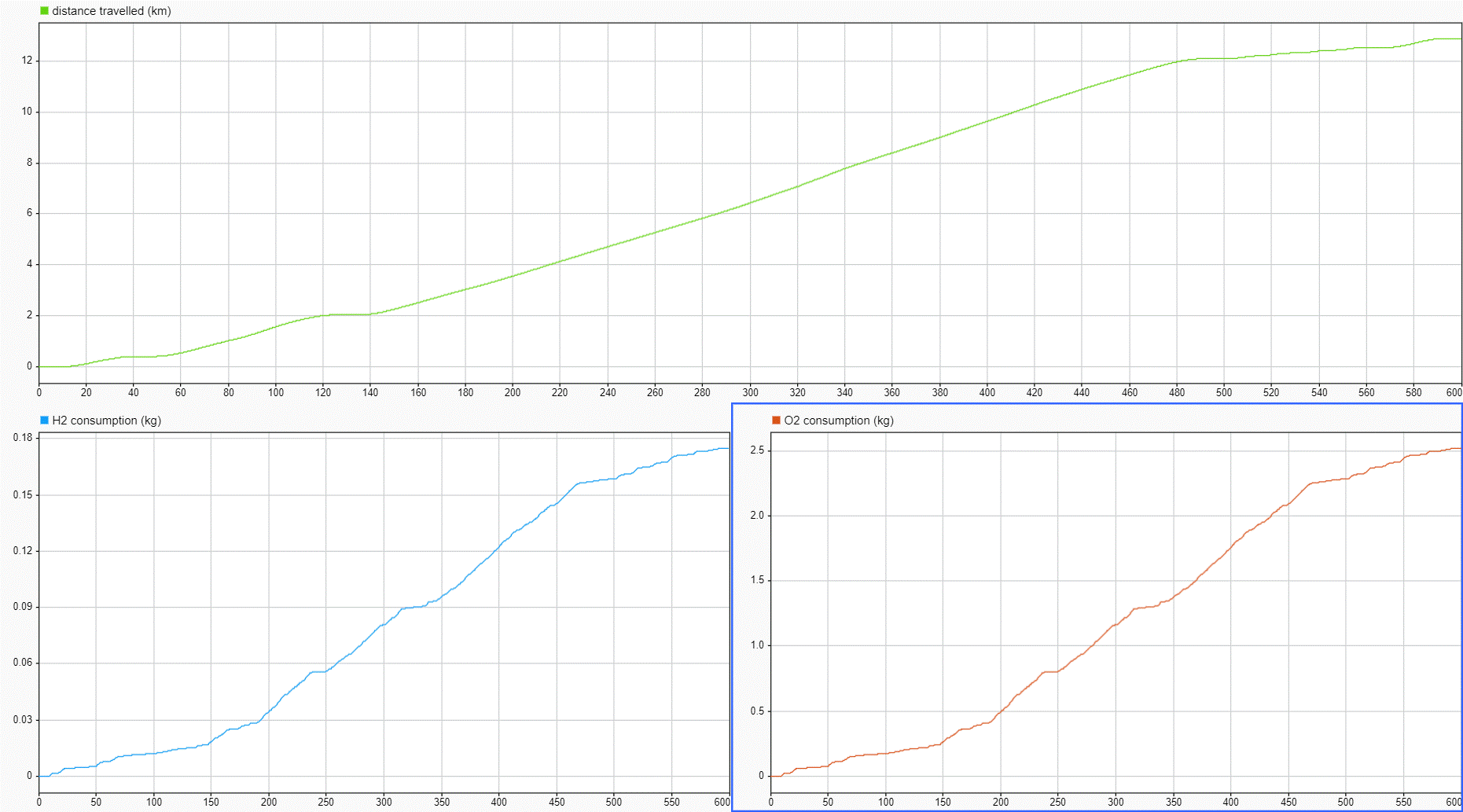
0.175kg of hydrogen has been consumed along with 2.5kg of oxygen to meet the power demand of the US06 drive cycle. A distance of around 12.9km has been travelled.
FCEVs of today consume about 1.6kg of hydrogen for 160km. Using that data, a US06 drive cycle distance of 12.9km should've used about 0.13kg of hydrogen. This model has used 45g of hydrogen more than the FCEVs of today. Although this validates the results, the model can be improved further to yield a better result.


